Description
- Patented technology, pinpoint current leakage fault with grounding resistance lower than 400kΩ
- Innovative dual-clamp for signal receiver, each clamp has two sizes of opening jaw for different conductors
- One pair of clamp working together, effective cancel capacitive interference when DC system is online
- Precise current direction (positive or reversed) indicating for leaking current help fast locate the faulty grounding
- 10Hz output frequency on signal receiver effectively avoids interference from DC system itself
- Signal receiver can set reference in different points for signal comparison, very fast for fault orientation
- Digital signal processing technology for detecting grounding resistance and capacitive resistance
- With built-in band pass filter to bypass different interference signals in the ambient environment.
- No disconnection of the electrical installation, ground fault location is carried out during operation
- Frequency spectrum analysis can test ambient frequencies, which helps analyze the surrounding environment.
- Signal generator with adjustable output voltage (24V~1000V) for different DC systems
- Multi-ways to indicate ground fault: sensitive current direction, phase angle, comparison of signal strength.
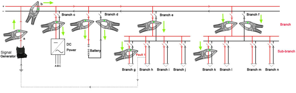
K-3836 uses comprehensive ways to pinpoint the faults with the following working rules:
- Signal generator has two testing leads connected with DC system. And it injects a low-frequency current signal with direction to the DC system. This signal will flow from testing lead to circuit, outflow from the faulty grounding point and finally flow back to the signal generator. This makes a return circuit that will be useful for signal tracing in the next step.
- Signal receiver will trace this current signal with the help of current direction judgment. Direction of current signal always goes to the faulty point. With one clamp on two busbars or two clamps respectively on two busbars, it could work effectively with strong anti-interference when system is online.
- Strength and phase angle of current signal will have big changes before and after the grounding fault. They also help pinpoint the fault.
Ground fault location | Output voltage: 24V, 48V, 110V, 220V, 500V and 1000V |
| Power supply | Signal generator: |
| Power consumption | ≥4 hours |
| Memory | 16MB |
| Display | Signal generator: 320×240 pixel 3.5″ LCD screen |
| Working temperature | -10℃~55 ℃ |
| Dimension | L420*W340*H14mm |
| Weight | 7.0 kg |
Q: What may happen if I don’t trace the signal fault in DC system?
A: Multiple grounds can occur on the dc system at the same time. This situation becomes critical when the combined ground resistance becomes so low that high-voltage circuit breaker control schemes are unable to open or close breakers when required or dc system circuit breakers and or fuses open due to over current resulting in de-energization of vital operating equipment.
There are some other bad consequences due to ground fault. Please click HERE for more consequences and solutions.
Q: What are the causes of DC ground fault?
A: Some common sources of low resistances to ground include:
- Moisture in conduit
- Junction boxes or switch/sensor terminations
- Wire splices soaking in water
- Degraded cable or wire insulation caused by aging
- Environmental conditions
- Wild habitat and constant abrasion from vibration
- Sharp objects piercing cable and wire insulation
- Wires that have pulled out of their terminations and touch ground or water
- Failed capacitors or semiconductor surge suppressors.
Q: What are the principles of tracing the signal fault?
A: There are 3 methods for signal tracing in circuit which is with earth fault:
1). Traditional Method: Sectionalization
Traditional ways of fault location in DC system involves sectionalization or interruption of DC branches to isolate the ground fault.
2). Current Injection
This method will inject a low-frequency AC signal and use this AC signal to locate the ground fault in the DC system.
3). Use Measurement Bridge
For online fault location, ground fault locator adopts the measurement bridge (switchable resistor) inside the signal analyzer to analyze voltage, current and grounding resistance. Then it uses signal detector to pinpoint the fault.
Q: What are the advantages of using switchable bridge (resistor) measurement?
A: It does not need injection of current signal to tested system and thus no relay tripping. It is more effective for fault location and safe to the tested circuits.
Q: How do you bypass the interference during live (online) signal tracing?
A: There is always interference caused by distributed capacitance in live (online) measurement. To bypass this interference and trace the fault faster, in firmware we use very low measurement frequency; in hardware, we use high sensitive current sensor for signal tracing.
Q: How do you avoid relay tripping during signal tracing?
A: We are using very low measurement current (lower than 5mA). This will not cause relay tripping in live signal tracing.