
Description
- Safe to use
For earth fault detection, the device uses low current of micro-amperes measurement signal and DC current clamp with high resolution. It has no interference to the tested systems. - High reliable designing
It adopts main system of 32-bit micro-processor. Hardware designing strictly follows EMC standard to ensure reliability of itself and its tested systems. - Precise measurementIt
Adopts high accurate current clamp for signal tracing and precise ADC for voltage sampling. This ensures the accurate measurement of voltage and resistance. - User-friendly interface
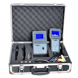
It has LCD display with vivid information indicating grounding status, waveform, insulation leveling, insulation resistance, leakage current, and direction of earth fault and so on. This user-friendly interface makes it easy and effective to use onsite. - Intelligent measurement function
- Signal analyzer can automatically identify system voltage leveling.
- When insulation resistance has any change, signal analyzer could quickly indicate the change.
- Distance will not affect the signal detection once the signal analyzer and detector are synchronized.
- During earth fault detection, current clamp could either clamp on single cable or multiple cables for faster and more effective signal tracing.
- Signal detector will indicate the direction of ground fault on screen once it detects any insulation problem.
- Signal detector and analyzer have wireless communication. Complete measurement could handle different types of insulation problem in DC system.
- Signal analyzer has different working modes like amplitude adjustment, frequency adjustment and waveform view which are suitable for different complicated applications.
- Measures voltage between DC system and ground ranging from 0 to 300V.
- Measures grounding resistance up to 999KΩ for both busbars and each branch circuit
- It detects and measures AC voltage which interrupts in DC system. Detection range is from 0 to 288V.
- It performs the function as accurate current meter with resolution up to 0.01mA.
- Arrow indication effectively helps users trace the signal and pinpoint the earth fault.
- Waveform display for tested circuit, indicating insulation status and current changes in tested circuit, it help users fast and effectively locate the point with earth fault.
- It tests and displays distributed capacitance in the system in real time. This helps users bypass the interference for earth fault detection.
- Fast signal positioning for the point of earth fault for both negative and positive busbars with the help of waveform and signal direction.
- Signal analyzer has different working modes like amplitude adjustment, frequency adjustment and waveform view which are very helpful for earth fault detection in high resistance grounding.
- The analyzing function of signal frequency spectrum effectively helps extract the testing signal amplitude which makes measurement more accurate.
Signal analyzer specification:
- Operation environment
- Working power: DC40V-300V
- Temperature: -20℃—55℃
- Humility:0—90%
- DC voltage measurement
- Measurement range:0-300V
- Resolution: 0.1V
- Accuracy: 0.2%
- AC voltage measurement
- Measurement range: 0-300V
- Resolution: 0.1V
- Accuracy: 0.5%
- Insulation resistance measurement
- Measurement range: 0-999.9KΩ
- Resolution: 0.1KΩ
- Accuracy: ≤±5%
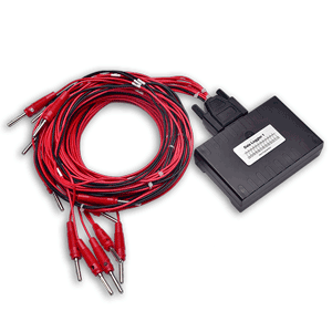
- Measurement Bridge:
- Adjustment range: 0mA, 0.25mA, 0.5mA, 1mA & 2mA
- Frequency range: 0.125Hz, 0.25Hz, 0.5Hz & 1.0Hz
- Grounding detection range: up to 200KΩ
- Distributed capacitance measurement
- Measurement range: 0-999uF
- Measurement waveform: square wave & sine wave
- Working mode: compulsory signal & automatic signal
- Display: 320×240 pixels TFT
- Power supply: powered by tested circuit
- Weight and dimension: 0.448kg, 200*145*75mm
Signal detector specification
- Grounding resistance measurement
- Measurement range:0-500KΩ
- Resolution: 0.1KΩ
- Accuracy: ≤±10%
- Frequency spectrum analysis
- Number of channel: 1
- Frequency range: 0.125-12.5Hz
- Resolution: 0.125Hz
- Display period of current waveform: 8s
- Measuring range for feeder: 0~2A
- Current measurement range: -100~+100mA
- Current resolution: 0.01mA
- Display: 320×240 pixel TFT
- Clamp jaw size: Ф30mm, Ф40mm and Ф10mm (optional)
- Power supply: 5V by 4 pieces of AA standard battery
- Weight and dimension: 0.303kg, 200**100*33mm
Wireless communication specification:
- Speed: 2Mbps
- Multi-frequency: 125 frequency points, suitable for multiple points communication and frequency hopping communication
- Very small size: built-in 2.4GHz antenna with dimension of 15x29mm
- Low power consumption: in answer mode communication, quick data transmission and starting time will effectively lower power consumption.
Q: What may happen if I don’t trace the signal fault in DC system?
A: Multiple grounds can occur on the dc system at the same time. This situation becomes critical when the combined ground resistance becomes so low that high-voltage circuit breaker control schemes are unable to open or close breakers when required or dc system circuit breakers and or fuses open due to over current resulting in de-energization of vital operating equipment.
There are some other bad consequences due to ground fault. Please click HERE for more consequences and solutions.
Q: What are the causes of DC ground fault?
A: Some common sources of low resistances to ground include:
- Moisture in conduit
- Junction boxes or switch/sensor terminations
- Wire splices soaking in water
- Degraded cable or wire insulation caused by aging
- Environmental conditions
- Wild habitat and constant abrasion from vibration
- Sharp objects piercing cable and wire insulation
- Wires that have pulled out of their terminations and touch ground or water
- Failed capacitors or semiconductor surge suppressors.
Q: What are the principles of tracing the signal fault?
A: There are 3 methods for signal tracing in circuit which is with earth fault:
1). Traditional Method: Sectionalization
Traditional ways of fault location in DC system involves sectionalization or interruption of DC branches to isolate the ground fault.
2). Current Injection
This method will inject a low-frequency AC signal and use this AC signal to locate the ground fault in the DC system.
3). Use Measurement Bridge
For online fault location, ground fault locator adopts the measurement bridge (switchable resistor) inside the signal analyzer to analyze voltage, current and grounding resistance. Then it uses signal detector to pinpoint the fault.
Q: What are the advantages of using switchable bridge (resistor) measurement?
A: It does not need injection of current signal to tested system and thus no relay tripping. It is more effective for fault location and safe to the tested circuits.
Q: How do you bypass the interference during live (online) signal tracing?
A: There is always interference caused by distributed capacitance in live (online) measurement. To bypass this interference and trace the fault faster, in firmware we use very low measurement frequency; in hardware, we use high sensitive current sensor for signal tracing.
Q: How do you avoid relay tripping during signal tracing?
A: We are using very low measurement current (lower than 5mA). This will not cause relay tripping in live signal tracing.
K-3838 Earth Fault Detector is widely applied in different DC system for ground fault location including:
- Railway and Transit: signal, communication, and locomotive electric equipment
- Power Utility: DC system with faulty grounding
- Industrial Facilities: electric safety equipment for general power distribution applications
- Telecommunication: electronic equipment with earth fault
Customers also viewed:
Basic model for quick fault location
Real time data logging in PC
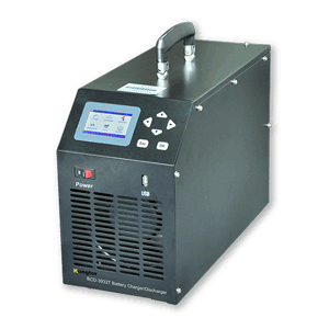
Battery regenerator for single cell